Introduction
The new Biobío railway bridge replaces an existing historic bridge, located between the towns of Concepción and San Pedro de La Paz, in central Chile. Built in 1889, it was at the time the first railway bridge to connect the two banks of the river in that area.
Throughout its long service life, the bridge has undergone various modifications to accommodate more modern trains, with higher axle loads and different types of traction. Repair works of varying scope have also been necessary due to damage to the structure. Although the maintenance and repair operations carried out have enabled the bridge to remain in safe service to the present day, given that it is a single-track bridge with a very narrow gauge and due to future capacity requirements, it has been necessary to undertake the design and construction of a new bridge in accordance with the most recent regulatory standards.
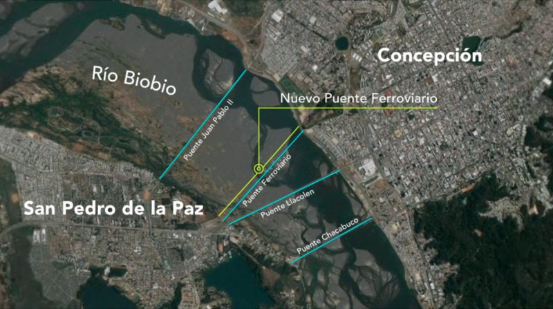 Location of the Biobío railway bridge
Bridge design
General concept
The original railway bridge consisted of a succession of 62 spans of around 30 m, with the exception of the two initial spans in the Concepción area, which are slightly longer. It was a single-track steel structure, comprising abutments with six piles and spans consisting of trusses on which the sleepers and rails are laid.
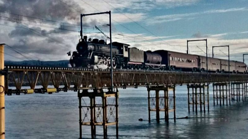 View of the original bridge
According to river mechanics studies, to ensure the best hydraulic behaviour of the Biobio River during floods, the new bridge had to be situated downstream of the original, with a straight plan layout, albeit slightly offset from the first, and the foundation piers had to be aligned with those of the existing structure. The distance between the two bridges ranges from 15 m in the San Pedro de La Paz area to 30 m on the Concepción bank, with the distance between support centres being around 30 m, except for the initial spans in the Concepción area, where the spans reach 45 m.
Despite the bridge’s considerable length (1,882 m), the new structure was straightforward, suitable for highly industrialised construction methods.
To capitalise on these industrialisation opportunities, various composite deck solutions were analysed. In this particular case, although two-way solutions were very promising, the required beam spacing to avoid compromising the transverse design and criteria relating to accidental loads led to the decision to use a double-action composite box girder.
Furthermore, with the aim of enhancing the bridge’s visibility and significance, EFE, the Chilean State Railways Company, requested the addition of an ornamental structure on the abutments.
 General illustration of the bridge and ornamental structure
Description
The new bridge is situated between kilometre 1+192 and kilometre 3+074 of the project, resulting in a structure 1,881.97 metres in length.
The bridge consists of a total of 62 spans with the following span distribution: 44.775 + 2 x 33.900 + 58 x 30.000 + 29.400. The two initial spans, as well as being the longest, are offset due to the existing road.
In plan view, the structure comprises a polygonal geometry of three sections that allow the curved railway alignment to be inscribed within a standard fixed-width deck of 14.60 m, with local widths of less than 13.80 m in the area of the abutments. The deck is wide enough to accommodate two railway tracks plus two pedestrian walkways for maintenance access. The tracks are laid on ballast.
The deck is of a composite type, consisting of a slab with a variable depth of up to 0.40 m and a steel box girder with a constant depth of 2.00 m. The webs are spaced 6.60 m apart, resulting in lateral cantilevers of 4.00 m for the upper slab. In the support areas, a lower slab with a depth of up to 0.40 m is provided to counteract negative deflections.
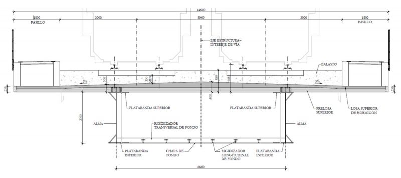 Typical deck section
The deck rests on seismic isolators that protect the infrastructure in the event of an earthquake, and seismic bars and stops are fitted at all abutments to ensure safety in the event of extraordinary seismic events.
Foundations
Three distinct zones can be identified along the route. Up to abutment C03, deep foundations can be constructed using piles with their tips resting on bedrock. In this first section, arrays of 4 x 2,000 mm piles have been used for internal supports and double arrays of 3 x 2,000 mm piles for joint supports, reaching depths of up to 29.50 m.
 Pile installation
Between pile groups C03 and C21, the soil is sandy with interlayers of non-plastic silt or silty sand. The piles are embedded in hard cohesive soils, and two rows of four 1,500 mm diameter piles have been used, reaching depths of up to 51.50 m.
The final section is situated in sandy soils of dense to very dense compaction. Rows of four piles, each 1,800 mm in diameter, have been used for the internal supports, and two rows of three piles for the joint supports, reaching depths of up to 41 m.
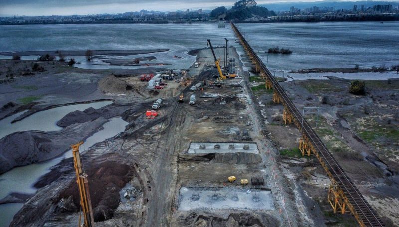
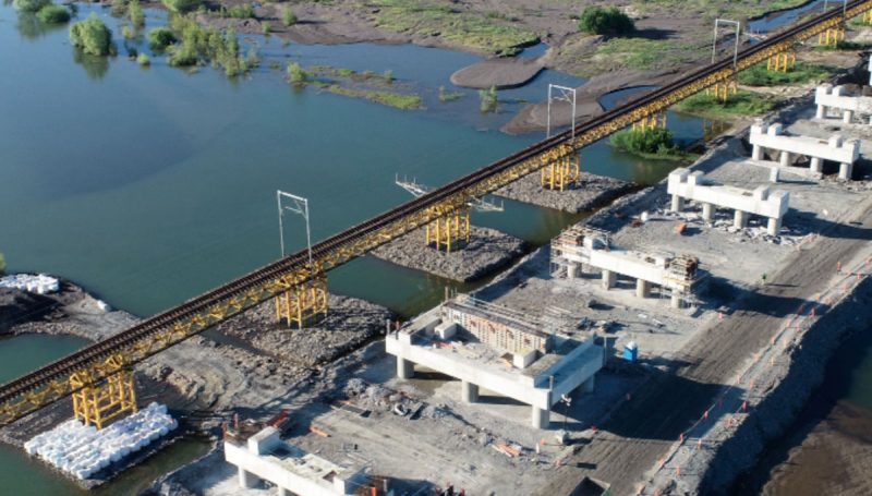 Overview of the weirs, section 3
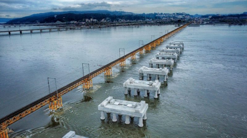 View of the pile foundations during the river’s flood season
As the pile caps are situated above the water level, the piles have an exposed or submerged section ranging from 3 to 8 m, plus a buried section of variable length. In the event of potential scouring, design scenarios had to be considered in which the exposed and buried lengths of the piles would undergo significant variations. For the structural design, a maximum scouring depth of 11 m was adopted, resulting in situations with free lengths between 14 and 19 m, in some cases coinciding with the accidental seismic scenario, which were the design-determining factors for the piles.
The piles have been designed using concrete with a characteristic strength of 25 MPa and steel with a yield strength of 550 MPa. The longitudinal reinforcement has been designed using Ø43 bars connected with couplers. The transverse reinforcement has been provided by Ø16 spirals (single or double).
Given that the position of the abutments could not be altered, that the height of the undercut could not be reduced, and that the embedment depth of the piles was constrained by the ground conditions, the use of seismic isolation devices was adopted to achieve technical and economic optimisation of the project.
The use of this type of device involves modifying the design spectra, significantly reducing the base shear forces by around 20–30%, which resulted in reductions in the amount of reinforcement in the piles of around 15%.
Deck
The deck, of a double-action composite type, has been constructed using a steel box girder with a constant depth of 2 m. Although the initial spans have significantly greater clearances and offset supports, the decision was taken to maintain the same depth across all spans by increasing the dimensions of the main beams and the thickness of the steel plates. Above, there is a 14.6 m wide concrete slab with a variable depth of 235 mm at the edges of the cantilevers, 300 mm in the support area at the webs, and 400 mm at the central axis of the deck.
The box girders are spaced 6.60 m apart with 4 m lateral cantilevers. The choice of the spacing between the webs, in addition to allowing for side cantilevers compatible with the non-use of elements such as ribs or struts, has been selected so that the outer tracks of each lane almost coincide with the box girders’ webs, thereby limiting transverse stresses. On the outer side, the box girders’ webs are stiffened with inclined cells.
In all cases, bottom slabs are provided in support zones, with a variable depth of between 200 and 400 mm, to improve the deck’s response to negative bending stresses. The bottom slab also improves the deck’s torsional response in the support zones, where torsional stresses are of greater magnitude.
The box girder is stiffened by lattice-type diaphragms every 5,000 mm and transverse stiffeners every 1,667 mm between diaphragms. The bottom plate has T-shaped longitudinal stiffeners every 900 mm, running continuously along the entire length of the deck except at the support bulkheads.
The support bulkheads, formed by double-web beams, allow for the connection of the seismic bars, provide continuity to the base slab, and extend outwards to form the contact surface with the seismic stops. Stiffening elements and transfer plates have been provided, which are necessary for the future replacement of supports.
At the top, there is a truss with cross-bracing between diaphragms. Once the upper slab has been constructed, this truss is no longer considered to contribute to the structural design.
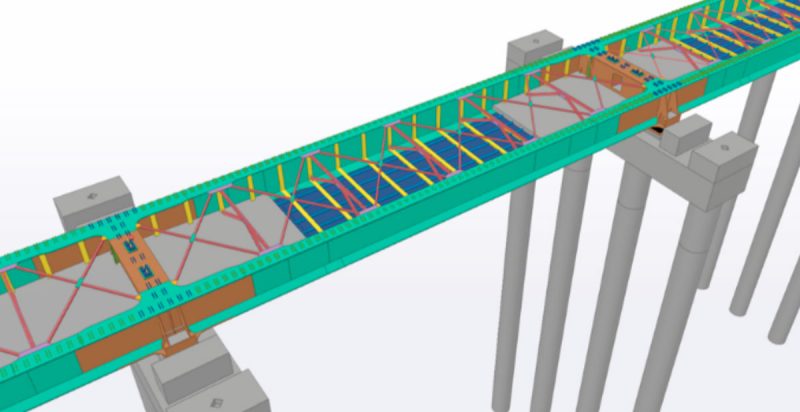 Metal box girder span
In order to achieve the simplest possible construction method, the upper slab of the deck has been designed using prefabricated ribbed precast slabs with a minimum depth of 80 mm in the valley areas and 180 mm in the central areas of the ribs. The precast slabs feature openings for connection to the metal box girder, for the connection of the seismic reinforcement bars, and for the passage of services.
 Installation of precast slabs
The steel members have been designed using ASTM A709 Grade 50 steel, with a yield strength of 345 MPa, and the passive reinforcement is ASTM A706 Grade 80 steel with a yield strength of 550 MPa. The concrete for the slabs is 40 MPa.
Seismic design
The new bridge is situated in an area of high seismic activity, with a maximum ground acceleration of 0.50g for the design earthquake and 0.75g for the maximum possible earthquake, for return periods of 500 and 1,000 years respectively. The design spectra were defined in accordance with the provisions of Chile’s MC-Vol.3, considering return periods of 475 and 1,000 years.
To improve the seismic performance of the structure and reduce the stresses on the infrastructure, it was decided to install elastomeric isolators with a lead core. These isolators are flexible elements, yet capable of supporting the structure’s vertical loads. The greater lateral flexibility of the isolators relative to the structure means that most of the lateral movements occur within the isolators, thereby reducing seismic accelerations by increasing the structure’s vibration period.
The inclusion of a lead core within the elastomer provides the structure with additional damping thanks to the energy dissipation provided by the core. This dissipation is achieved through the elastoplastic behaviour of lead and its rapid crystallisation, which allows the unloading following plasticisation to occur elastically. The analysis of the seismic isolators was carried out using the multimodal spectral methodology, where isolation is achieved by applying an effective stiffness to the isolator and damping, thereby reducing the response spectrum for the isolated periods.
Taking into account the characteristics of the bridge and the ground, three different types of isolators were ultimately installed in the structure, achieving reductions in stresses on the pile caps of around 20% due to the dissipation effect. Additionally, seismic movements at joints have been reduced due to the contribution of the lead’s stiffness, as well as movements under rapid loads (braking, uplift or wind), since the lead does not reach plasticity under these actions, its stiffness being far superior to that of elastomer. Greater overall damping of the structure is also achieved.
The seismic bars constrain the deck and prevent extreme movements in the event of large-magnitude earthquakes. The connection detail between the deck and the abutments usually employed involves placing the bars embedded on both sides of the supports. Although this arrangement has proven effective, it presented certain drawbacks that made its use in the case of this bridge inadvisable.
In the design, it was decided to use connections for the bars that would allow the deck to move freely during normal service and design earthquakes, so that the isolators could function freely up to their design limit. Only in extreme cases do the bars constrain the deck longitudinally.
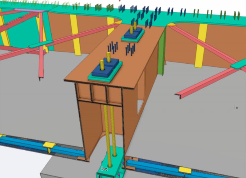 3D view of bar connection
Reinforced concrete abutments are provided in the transverse direction to prevent the deck from losing its support in the event of extreme seismic events exceeding those taken into account in the general design.
Road-structure interaction
In the design of the new bridge deck, expansion joints have been provided at intervals of no more than 180 m (expandable length equal to 90 m), as this is the distance beyond which it cannot be guaranteed that stress variations in the rails will remain within acceptable limits. Notwithstanding the above, given certain unique features of the structure and the use of seismic isolation devices, track-structure interaction analyses have been carried out in accordance with the requirements of Eurocode 1 (EC1) and UIC-774, concluding in all cases that there is no need to install track expansion joints.
Construction
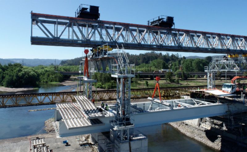
For the construction of the piles, abutments and piers, temporary land spurs were used in all cases, enabling construction using conventional methods. Once these elements had been completed, the deck was installed either using self-propelled cranes in specific instances or using girder-launching equipment designed specifically for this project.
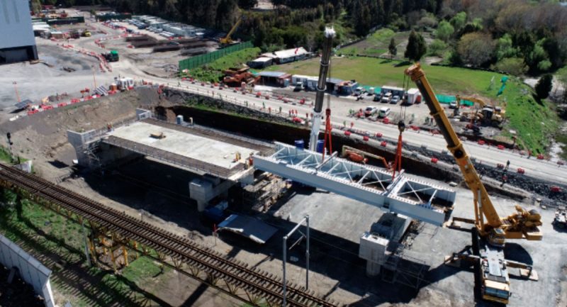 Installation of the initial span using self-propelled cranes
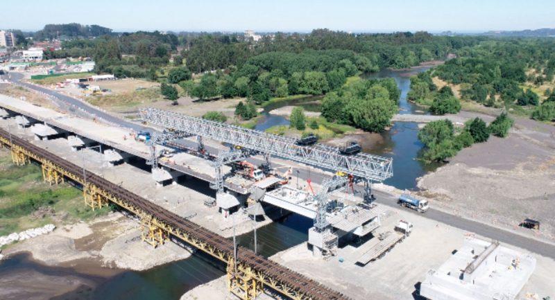 Span assembly using girder launchers
Conclusion
In November 2025, the second phase of the commissioning of the new railway bridge for the Biobío region was completed, which now enables the passenger trains to connect Coronel and San Pedro de la Paz with Talcahuano, Hualpén, Concepción, Chiguayante, Hualqui, San Rosendo and Laja.
Similarly, this structure supports the movement of freight to the various ports, contributing to the economy and development of the region and the south of the country, whilst also becoming a new architectural landmark for Gran Concepción and the Biobío region.
The railway bridge allows speeds of up to 100 km/h for passenger trains and 65 km/h for freight trains. It is earthquake-resistant and can withstand rises in river levels, ensuring the continuity of the railway system whilst strengthening and developing it.
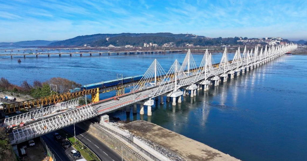
 View of the bridge in operation