Introduction
Commissioned by the mining company VALE, ENGECORPS has developed the conceptual design to reinforce the Maravilhas II dam, implementing measures to ensure the dam’s safety and compliance with current technical regulations.
Among the alternatives studied, the selected option involved reducing the operational water level of the reservoir by lowering the spillway threshold and constructing a new spillway with greater discharge capacity.
The Maravilhas II dam has for years retained the mining tailings generated at the Pico mine and currently, as well as retaining the accumulated waste, it receives sediments from the upstream area, accumulates water for mine recirculation and promotes the clarification of the final effluent to bring it into line with environmental regulations before it is discharged into the downstream stream.
In an independent audit carried out in 2019, taking into account the piezometric conditions recorded in the dam monitoring, the dam stability analyses indicated that the safety factors were lower than those acceptable according to technical regulations.
With the aim of increasing the dam´s safety, a series of interventions were proposed, including reducing the height of the dam and smoothing its downstream slope, with the construction of a new spillway located on the right abutment of the dam, returning the effluent flows from the reservoir directly to the stream, downstream of the mouth of the watercourse where the dam is located.
Over the years, a process of deep erosion had occurred in a natural drainage channel near the right abutment of the dam, affecting the entire hillside. In order to stabilise this area, the eroded region was remodelled using soil from the excavations necessary for the construction of the spillway.
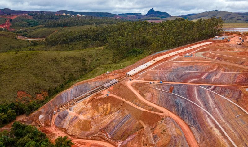
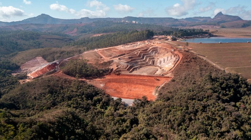
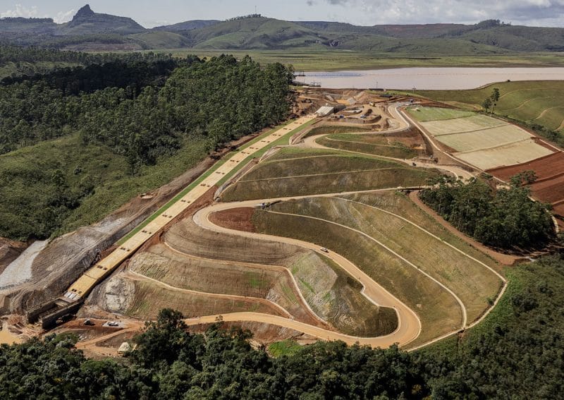 Spillway at the end of construction, with the dam and its reservoir in the background
Structure characteristics
In order for the new spillway to be operational, it was necessary to build a channel connected to the reservoir intake structure, located on the right abutment of the dam. The main structure is made of reinforced concrete, consisting of a control structure equipped with cofferdam gates, followed by a stepped weir, ending in a stilling basin, so that the channel restores the flow in an orderly manner to the Congonhas stream.
Based on the study of the flood control of the tributaries to the dam reservoir, the maximum effluent flow of 80.9 m³/s was obtained for the maximum probable precipitation (MPP).
The drainage system has a difference in elevation of approximately 88 m between the water level in the dam reservoir and the stream bank. The steps are 1.0 m high and the length of the platforms was adjusted to accommodate the terrain profile.
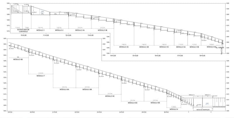
Spillway – Longitudinal profile of the stepped weir
As for the geology of the spillway area, it has colluvial soils superimposed on the saprolitic soils of the Fecho do Funil and Taboões formations, mainly composed of dolomitic phyllitic lithology, as well as alluvial deposits on the banks of the stream.
Excavations for the implementation of the spillway removed the colluvial soils on the slope, supporting the structure directly on the saprolitic soils. On the banks of the stream, the alluvial deposits were partially removed, the section downstream of the stilling basin replaced with rockfill, and with root-type stakes to mark the perimeter of the treatment area.
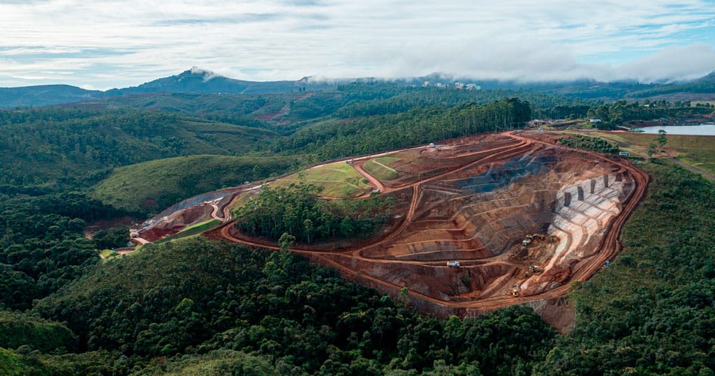
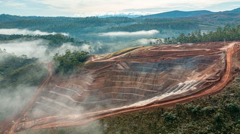
 View of the excavations for the spillway with its construction accesses
Due to the proximity of the urban area, the owner requested that the rapid step be equipped with a cover slab for acoustic reasons. Thus, on the hillside, the structure consists of a closed gallery section with three compartments, which runs from Module 1 (downstream of the control structure) to Module 9 (upstream of the buffer basin).
A drainage system was installed in modules 1 to 9 to relieve possible internal pressure on the foundation (underpressure). In modules 10 and 11, corresponding to the surge basin, the structure was dimensioned to withstand hydraulic underpressure, as well as unbalanced earth thrust forces between both sides.
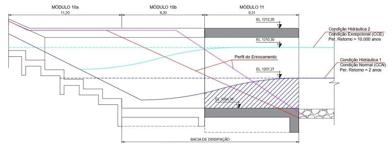
Structure of the spillway surge basin – Hydraulic profile and earth thrusts
3D numerical modelling
The 3D numerical modelling of the spillway comprises the hydraulic structure from the conveyance channel to the control structure, the stepped weir and the stilling basin. Due to the dimensions of the system, and taking into account the level of detail required for the physical phenomena to be correctly represented, the simulations were divided into three sections:
- First section: begins on the right bank of the reservoir with the conduit, the control structure and the first four steps.
- Second section: consists of one of the compartments of the rapid, given that the geometry is the same and the flows are approximately the same.
- Third section: consists of the three compartments of the rapid in steps and the buffer basin.
The software used for the 3D numerical model of the hydraulic simulation of the spillway was OpenFOAM, which is based on computational fluid dynamics (CFD). CFD is an area of fluid mechanics that uses numerical analysis and data structures to analyse and solve problems involving fluid flow, processing the calculations necessary to simulate the movement of fluids (liquids and gases) and their interactions with surfaces or objects defined by boundary conditions using a computer.
The results of the simulations for section 1 show that, in the control structure, the water velocity increases in the contractions for water collection in each of the compartments. In the stepped section, vortex formation is observed at each step, as predicted in the design, with the formation of a skimming flow regime. The flow always remains free, both in the open channel section and in the closed channel section.
The results of the simulations for section 2 show the pressures along the steps, with negative pressures immediately downstream of the edges of all the steps, due to the contraction of the flow caused by the vortices generated in them, followed by an increase in pressure due to the impact with the bottom of the steps.
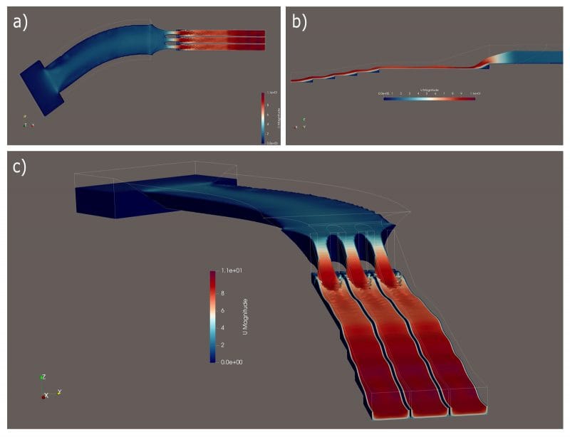
Results of Section 1 – Speeds: a) plan view; b) longitudinal profile; c) isometric view
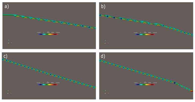
Results for Section 2 – Pressures: a) segment 1; b) segment 2; c) segment 3; d) segment 4
Two simulations were performed for section 3: Scenario A to verify the free edge considering the maximum NA in the stream, and scenario B to verify the containment of the hydraulic jump inside the buffer basin for the minimum NA in the stream. The simulation results show, in scenario A, the existence of a free edge of 1.0 m at the end of the buffer basin, with a good amount of air in the flow in the turbulent zone, while in scenario B, the formation of the hydraulic jump inside the buffer basin is observed, developing freely without escaping towards the return channel or towards the stream.
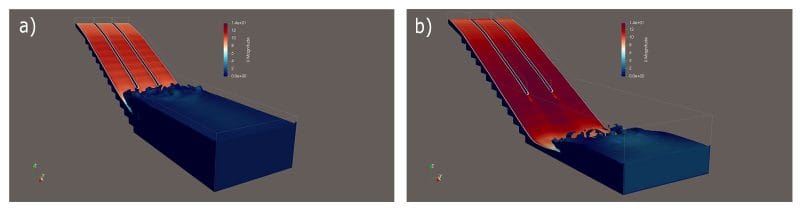
Results for Section 3 – Speeds: a) scenario A; b) scenario B
The results of the 3D numerical simulations developed in OpenFOAM attest to the good hydraulic performance of the spillway structure: the conduit channel has adequate dimensions, the flow is divided in an orderly and equitable manner in the control structure, the height of the stepped weir is sufficient for the maximum flow rate, even in places where some flow oscillations occur due to the change in longitudinal slope, the minimum free edge was respected in the stilling basin, and the hydraulic jump was contained within the length of the structure.
Based on the results of these studies, it was decided to install aeration pipes at the base of the steps to prevent the formation of negative pressures that could cause cavitation on the walls and at the base of the steps. In addition, windows were installed in all modules to allow for inspection and possible repairs.
Spillway construction
The project includes an access route for construction that runs from the crest of the control structure to the side of the surge basin. This access allows maintenance along the entire spillway staircase, with intermediate access points to the gallery roof.
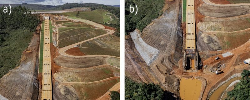
Access for construction/maintenance on the spillway. a) upper section; b) lower section
Once the dam had been built and the reservoir filled, the spillway works had to be properly protected against possible rises in the reservoir level upstream. Similarly, the works on the bank of the stream had to be planned to maintain protection against flooding in the work area downstream.
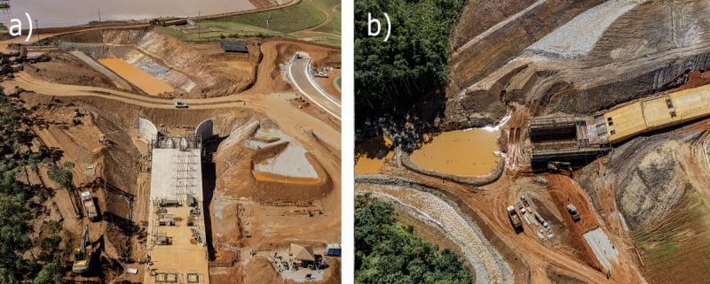
Work areas protected against flooding a) upper section; b) lower section
In order to restore the flow discharged from the Maravilhas II dam reservoir, it was necessary to carry out works on the bed of the Congonhas stream, reconfiguring its banks and widening its channel. The entire section of the intervention was protected with rockfill of a diameter compatible with the expected flow velocity for a 100-year recurrence period flood.
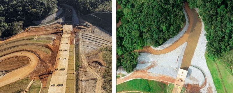
Interventions on the Congonhas stream bed in the vicinity of the buffer basin
This spillway began operating in the fourth quarter of 2025 and experienced its first wet hydrological period in early 2026, with heavy rains, performing satisfactorily and consistent with the assumptions and parameters adopted in the design.
Recovery of the eroded area
The works to increase the safety of the mining dam included the recovery of an extensive eroded area on the hillside, between the right abutment of the dam and the new spillway to be built.
The hillside underwent an evolutionary process due to the emergence of the water table in soil with erosive potential. The walls of this ravine were unstable, with landslides occurring during periods of rain. At the start of the interventions, the affected area covered 250 m, with a depth of up to 40 m and a surface width of 86 m.
To recover the eroded area, the first step was to stabilise its walls by excavating and smoothing the slope, with a total excavation volume of 90,000 m³. These excavations allowed safe access to the bottom of the gully for the installation of an internal drainage system, composed of sand and gravel, which was covered with fill composed of soil from the excavations necessary for the spillway.
 View of the excavations carried out to stabilise the eroded area
The excavations reached the right bank of the stream, where rockfill was placed at the base of the recovered area, receiving the flow collected in the drainage at the bottom of the gully, including some contributions from water outcrops on its walls.
After the excavations stabilised the ravine, a layered soil fill was constructed from the base to the crest over the previously executed bottom drainage. A total volume of 300,000 m³ of fill was placed, consisting of soil, sand, gravel and rockfill.
 Fill in progress in the eroded area, with the dam and spillway in the background
The recovered area was covered with grass, fully integrating it with the natural morphology of the slope. A surface drainage system collects rainwater, directing it in an orderly manner to the edge of the stream, preventing possible new erosion processes.
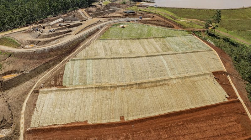
Recovered area with surface drainage and turf covering completed
Final Considerations
The implementation of the reinforcement works has improved the stability conditions of the Maravilhas II mining dam, in accordance with the regulatory requirements set forth in current legislation. With these interventions, the dam has achieved emergency level closure by the National Mining Agency (ANM), receiving a positive Declaration of Stability Condition (DCE), a technical document that certifies the safety of the structure.
The construction of the new spillway, with the reduction of the reservoir’s operating water level and the increase in its drainage capacity, has been carried out in parallel with the dam reinforcement works, which include reducing the height of the dam, smoothing its downstream slope and treating the foundations at the base. At the same time, the works to recover the eroded area have allowed the natural slope to be remodelled, increasing safety and making use of the excess volumes from the excavations necessary for the construction of the new spillway.
The designs for the new spillway and the restoration of the eroded area were developed by ENGECORPS, in parallel with the dam reinforcement project, which was carried out by another Brazilian company. It should be noted that these designs were verified and certified by an international consulting firm, which attests to the quality of the work carried out.